Objective: repair a 90 year old AM radio..and do it without electrocution nor causing a fire – yeah, it’s made out of wood.
Radio was the big new thing for the general public in the Roaring 20’s. Retail sales exploded in the early part of that decade, and sales and innovation went wild up until the stock market crash in October of 1929. This event thinned the heard of the many smaller radio producers, who often offered gimmicks with fancy names to sell radios.
The typical radio of the early 20’s was a mess to set up, operate, look at, maintain and wear. Yeah, check out those headphones.
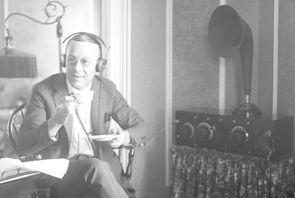
Here’s a typical setup: Radio with multiple tuning dials, ugly horn speaker with tinny sound and low volume. Under the radio behind that curtain are likely numerous quart-sized batteries. Also not shown is the really long wire aerial and ground wire needed..and ostensibly you had to wear a suit to listen in to whatever stations you could pick up.
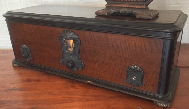
RCA and other producers wanted to simplify the radio setup, have better performance, easy operation and make the contraption look attractive. One such example is the RCA Radiola model 60 made in 1927. This set boasts single dial tuning, integrated power supply so it could be plugged into an AC lamp socket, a single control for volume, and a patented circuit that was very sensitive (pulling in distant stations) than competitive sets – truly innovative. This model was enormously popular and one article estimates over 100,000 sold. It’s also a battleship: 35lbs in weight, and 30” wide. Check out the beautiful cabinet with fancy escutcheons!
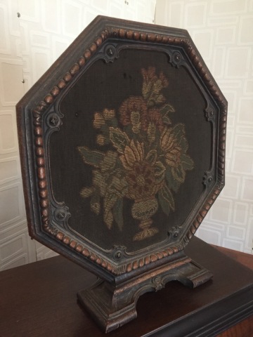
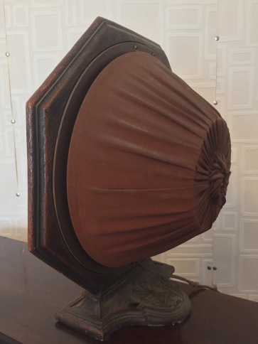
I was able to find the matching speaker atop from a collector in Pa. Yes, that thing with the floral knitted tapestry is the speaker. I’m very lucky to have found this radio in good cosmetic condition. After repairs it turned out to be a well-playing AM radio, with great volume and minimal AC hum.
With a long wire antenna and good ground connection I was able to pick up a French AM station – Montreal? No comprende-obviously. The minor drawback is the tuning scale is in a relative scale of 1-100, and the frequency division of the broadcast band (540 – 1600 kHz) is non-linear over the scale range, so I have to hunt for stations. For example, at the high end of the band – divisions 90-100 spread over a tight 300 kHz and the low end at 0-10 dial spread is 50 kc! However, we’re doing well at 90+ years old.
The radio wasn’t operational when I got it, and this story documents the servicing effort – believe it or not, there are other people out there fixing these things. And by “people” I mean distinguished gentlemen of a certain age.
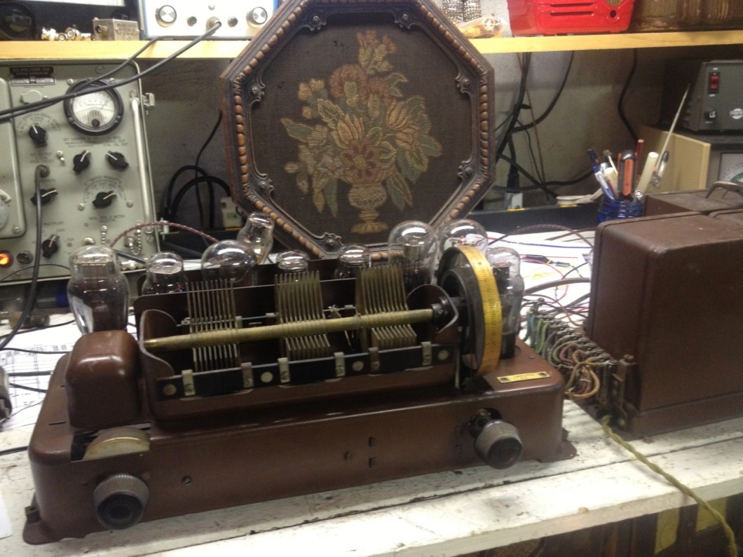
Here are the major components; note the power supply unit on the right. This is referred to as an SPU (“Socket Power Unit”) and was made to be screwed into a lamp socket – they didn’t have a lot of electrical outlets in those days; there were very few appliances! Connected by 12 or so wires on the left is the chassis, and atop with the wheel on the right side is the tuning condenser and it’s mounting tub. Notice the tops of the glass vacuum tubes behind it.
Repairs
After some research, I located the service-alignment instructions and the schematics. The immediate problem was that the tuning mechanism was frozen.
A common problem in these models is expansion of the tuning wheel; they are molded from “pot” metal, a mixture of lead and anything else laying around at the time of manufacture got tossed into the pot, so quality control was poor. Over time, the metal expands and deforms, and the wheels freeze – I’ve owned four or five of these radios and the tuning wheels all have required repair. I repaired this one by drilling out the brass pin holding it in place and replacing it with a set-screw. I broke the first one; the pin is tapered and set at an offset to center. Drilling out brass surrounded by lead is challenging to do by hand. Once that was turning freely, it was time to address the electronics.
The schematics did not list parts all of the values, so I took some time to identify components before getting out the soldering iron. The parts nomenclature below matches the labeling on the schematic.
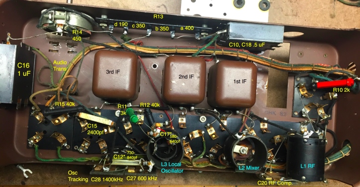
Figure 6: Chassis underside with nomenclature
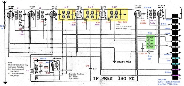
Figure 7: Updated chassis schematic
Several capacitors were not labeled and their values are important for oscillator and tuning operations. I measured these using an Impedance bridge. Two paper capacitors, and a couple of the “dog-bone” style resistors were replaced.
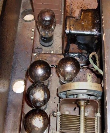
Replacing the power suppy filter capacitor bank was a must-do! Here’s what can happen if you don’t. Check out the filter choke explosion – tar splattered everywhere.
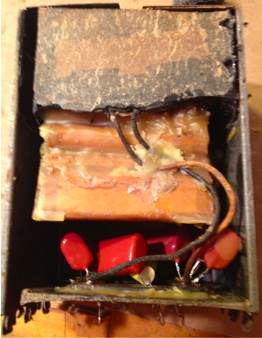
Removing the capacitor bank from the small chassis wasn’t too difficult. The trick was opening the box. The best solution was to tap one side of the box up, sliding it off to reveal the components. The capacitor bank popped right out, and I reused some of the beeswax potting to install the new capacitors – see the small orange units on the right side. Notice the black thing on the top, that’s the filter choke, potted in tar.
Another important note: Be cautious with the flat metal capacitors unless you have problems during testing. Only one of these is labeled in the literature, 2400 pf, and the others may have been “picked” values; i.e. chosen by the worker at build-time when testing the radio. (I did not examine the fixed capacitors within the three IF transformer boxes). Since working on a second model, I found the capacitance values are slightly 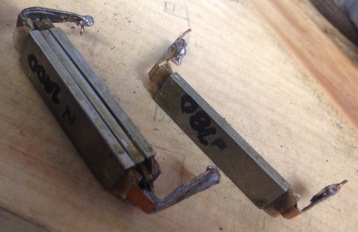 different – that could be because of aging or by selection at build time. These are made with copper plates and the dialectric is some kind of fish-paper, and the whole works are wrapped in steel, and the copper ends protrude and are soldered together. Repetitive bending can break the contacts. C15 in the chassis view above is example.
Tube selection had interesting results. Although I like the look of the older globe-shaped 27’s there was significantly better performance from the newer shouldered-shaped tubes. Once at tube is placed in the radio and the alignment is performed, the tubes should not be swapped into different positions or you’ll have to redo the alignment and neutralization procedures. These vacuum tubes are still easy to get!
Service Alignment
The alignment procedure is unusual (assuming you’ve done this on other radios) and calls for removing the large tuning condenser in it’s mounting tub to access the tuning screws to peak the IF transformers. This process took some experimentation as I needed to find a nonmetallic screwdriver, and the instructions for neutralizing (offsetting the effects of inter-electrode capacitances within the vacuum tubes) didn’t work for me. I kept having oscillation problems, and the original alignment instructions call for neutralizing with a dummy 27. A whuuut? This is a dud ’27 tube with a filament pin cut off to account for the inter-electrode capacitances present in the tubes. I tried this, and using headphones, couldn’t detect a Null – or hear anything for that matter but static. The servicing instructions are available at the link below.
I then connected an oscilloscope on the grid of the 2nd detector and peaked the IFs by maximizing the size of the modulated waveform. I found that by alternating between the IF adjustment and Neutralizing better peaking of the waveform could be realized. Tuning too far it would begin to oscillate – which could be seen on the scope. Once things were in the ballpark, I realigned using the called for dummy 27 approach and it worked well.
I replaced the tuning condenser and got stations immediately. The dial scale is relative units from 0 to 100, and peaking the 600, 1400 kc endpoints was problematic. I was not able to get any stations at the low end, and coupled a frequency counter to the oscillator tuning capacitor. i was expecting to get 780 kc at the low end, to get a difference frequency of 180. It was significantly off. The solution was to replace one of the copper/brass flat capacitors in the local oscillator with 680+10 pf NPO ceramic disk (value by experimentation), I was then able to set the bottom end point.
I then turned my attention to the audio section that was noisy, cleaned the pot, and tested different 71s until the best gain was realized, and the volume on this thing is impressive! Rock out to 1010 WINS!
Another point to mention: After connecting the SPU to the chassis with tubes I compared my vdc readings to a service manual and found mine were significantly higher. Later, (after first tuning attempted) I installed a 390 ohm 1 watt to reduce the B+ feed, then added a couple more resistors to bring down the some of the tube plate voltages.
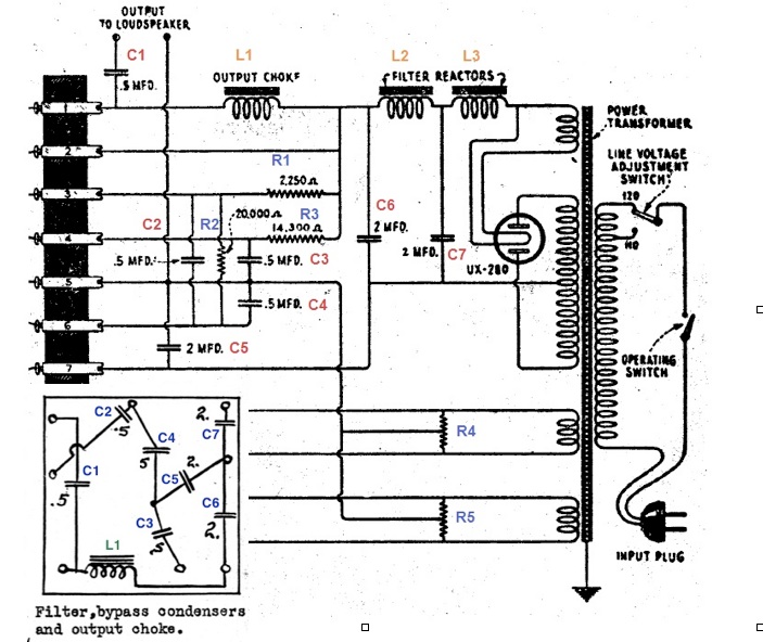
Figure 11: Updated “SPU” power supply schematic
This radio turned out to be a good performer, recieving a lot of stations, though “images” of a given station at different points on the dial.
Email me for further info!
References
Radiola 60 technical discussion – starts on Sheet 10
